Boilers & steam systems · Project notes
Boiler Burner Start-Up Sequence: What Happens Before the Flame Lights
The job
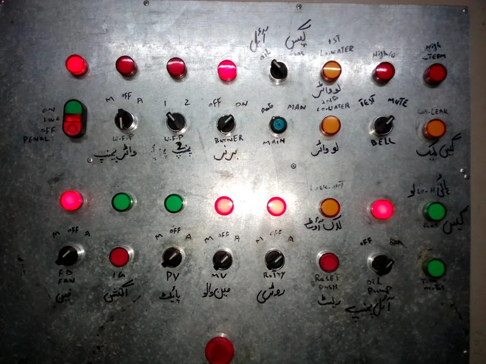
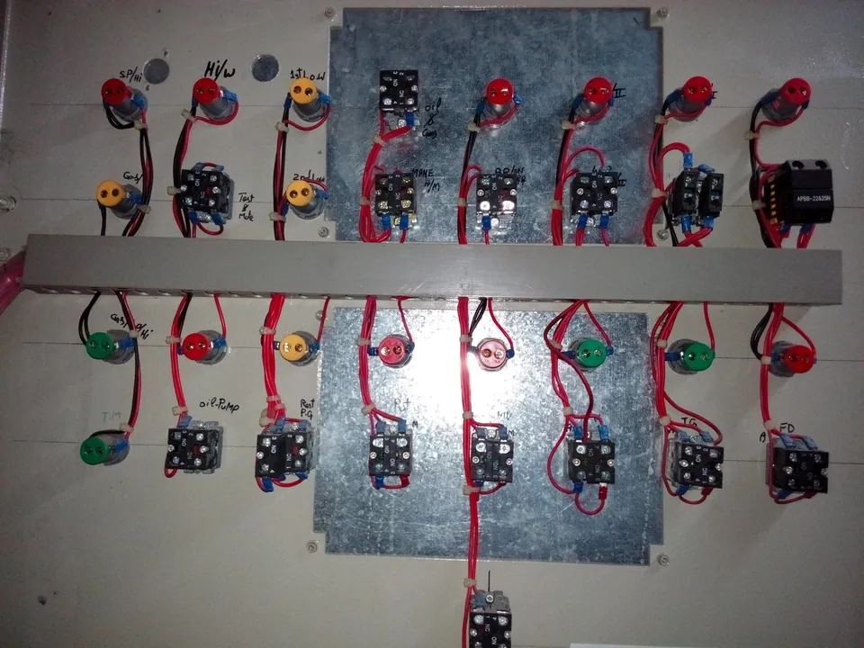
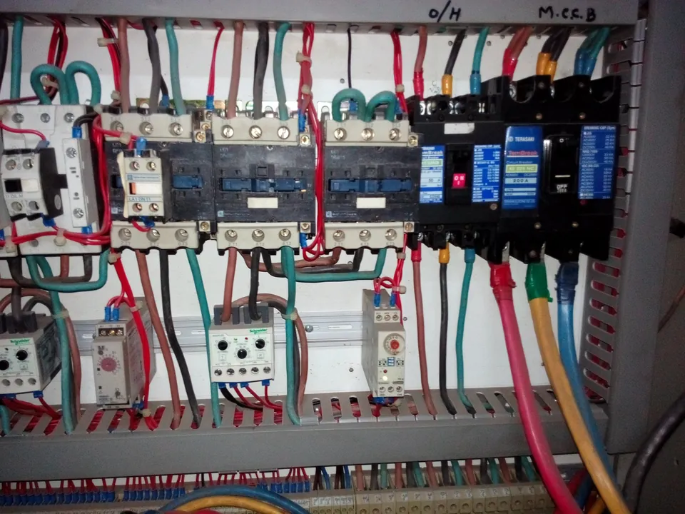
This page comes from a burner control panel we documented, wired, programmed and tested for a gas-fired steam boiler. The work ran from the drawings and the field instrument list through panel wiring, PLC logic and the operator panel to signal testing and a full test of the firing sequence. The photos are from that panel.
When a burner refuses to light, or lights and then locks out, the operator usually sees one red lamp. Knowing the order of the start-up sequence tells you which step the burner stopped at, and that tells you which switch, valve or sensor to check first. That is what this page sets out.
The start-up sequence, step by step
The burner moves to the next step only when the feedback for the current step arrives. If the feedback does not arrive in time, the burner control unit stops the sequence and locks out.
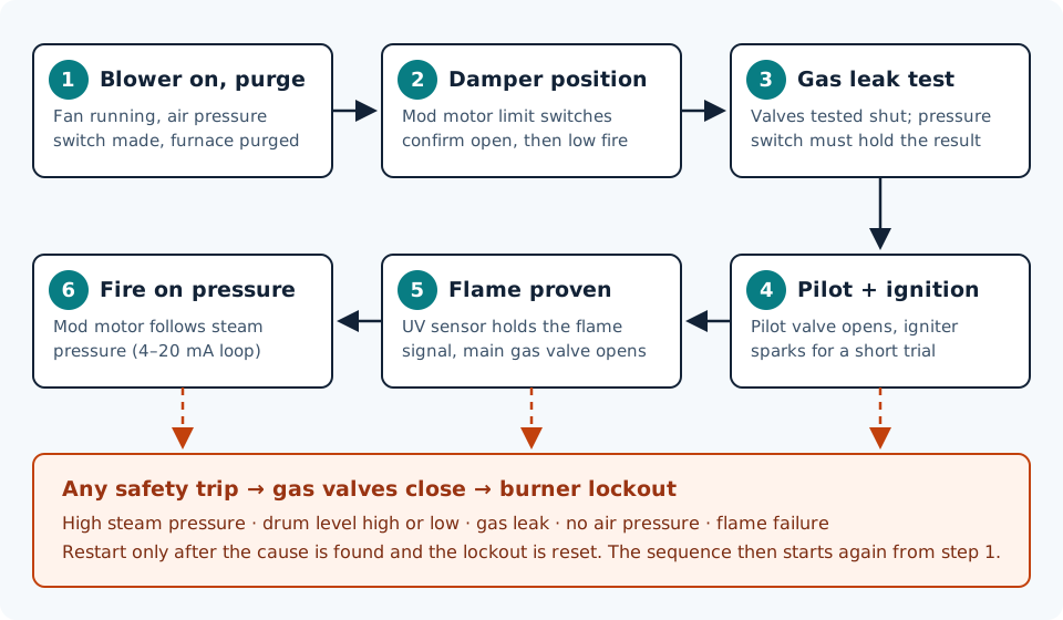
1. Blower on and purge
The forced-draught fan starts first. The contactor sends back a run signal, and the air pressure switch must make to prove that air is actually flowing, not just that the motor is energised. The fan then purges the furnace and flue so that no unburnt gas is left from the last firing. The purge time is set by the burner manufacturer and the applicable standard; it is not something to shorten on site.
2. Damper position proven
The modulating motor drives the air damper (and on this burner, the fuel linkage) through its range. Its limit switches tell the logic where it is: fully open for the purge, then back to the low-fire start position for ignition. If the start-position switch never makes, the burner waits here. A slipped linkage or a mis-set cam is the usual cause.
3. Gas valve leak test
Before any gas reaches the burner, the logic checks that the safety shut-off valves are tight. The valves are opened and closed in a set order, and a pressure switch on the pipe section between them has to show that pressure is held, or stays vented, for the test time. If a valve is passing, the pressure changes, the test fails and the burner does not continue. This step is what stops a leaking valve from filling a cold furnace with gas.
4. Pilot valve and ignition
The pilot gas valve opens and the ignition transformer sparks the electrode. This trial for ignition is deliberately short. If no flame is seen before it ends, the pilot closes and the burner locks out rather than trying again on its own.
5. Flame proven, main gas valve opens
The flame sensor (a UV cell on this boiler) has to see the pilot flame and keep holding the flame signal. Only then does the main gas valve open. From here on, the flame signal is supervised continuously: if it is lost, the gas valves close within the safety time of the burner control unit.
6. Firing rate follows steam pressure
Once the main flame is established, the burner is released to modulation. A pressure transmitter on the steam drum sends a 4–20 mA signal, the pressure control loop compares it with the setpoint, and the modulating motor moves the burner between low and high fire. A second loop holds the drum level by controlling the feed water.
Safeties that stop the burner
Each safety is wired so that the safe state is the de-energised state: a broken wire or a lost supply also stops the burner. Every one of them must close the gas valves and hold the burner in lockout until someone resets it.
| Safety | Signal from | What it protects against |
|---|---|---|
| High steam pressure | Pressure switch on the steam drum | Pressure above the working limit, before the safety valve has to lift |
| Drum level low (1st and 2nd low water) | Level switches or level transmitter | Firing with the tubes uncovered, the most damaging boiler failure |
| Drum level high | Level switch or level transmitter | Water carried over into the steam main |
| Gas leak / valve leak test | Pressure switch between the gas valves | Gas passing a shut valve into the furnace |
| Gas pressure low and high | Gas pressure switches on the gas train | Unstable flame or flame failure from wrong supply pressure |
| Air pressure | Air pressure switch on the fan | Firing without combustion air |
| Flame failure | UV flame sensor and burner control unit | Gas flowing with no flame to burn it |
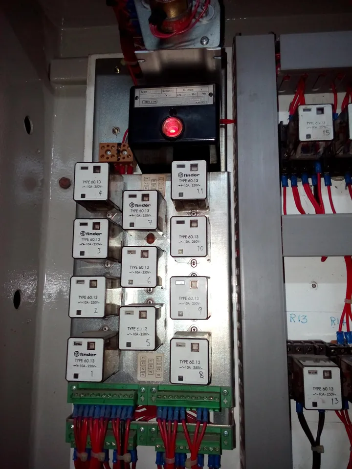
A note on PLCs: the PLC on a job like this runs the sequence, the interlock logic and the operator indications, but the flame supervision belongs to a dedicated burner control unit (flame safeguard) built and certified for that purpose. A general-purpose PLC is not a substitute for it.
Where to look when the burner stops
Note which step the burner reached before it locked out. That narrows the search to a few devices.
| Stops at | Likely cause | Check first |
|---|---|---|
| Fan running, no purge | Air pressure switch not made | Fan rotation, blocked air inlet, switch setting and sensing tube |
| Damper position | Limit switch not reached | Modulating motor supply (24 V AC here), linkage, cam and switch setting |
| Leak test | Valve seat passing or pressure not held | Valve seats, vent valve, gas supply pressure, test pressure switch |
| Ignition trial | No pilot flame | Electrode gap and HT lead, pilot gas pressure, pilot valve opening |
| Just after the main valve opens | Flame signal lost | UV cell dirty or badly sighted, gas pressure dip, air/fuel ratio |
| While firing | A safety tripped | Steam pressure, drum level, gas pressure switches; read the lamp first |
Every signal on one sheet
Before the panel was built, every field device was listed against a terminal number. The sheet below became the reference for wiring, loop checks and later fault-finding. It covers the neutral links, the water level switches, the door and air pressure switches, the ignition, pilot, main and vent valve outputs, the gas high and low test switches, the UV flame sensor, the modulating motor limit switches, its 24 V AC supply and 4–20 mA position signal, and the 4–20 mA measurement signals.
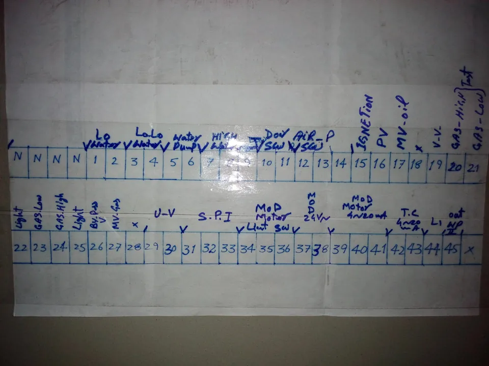
| Group | Signals |
|---|---|
| Water level | Low water, low-low water, high water, feed water pump |
| Burner proving | Air pressure switch, door switch, modulating motor limit switches, UV flame sensor |
| Gas train | Gas low and gas high pressure switches, leak test, main gas valve, bypass valve, vent valve |
| Ignition and fuel | Ignition transformer, pilot valve, main oil valve (dual fuel) |
| Analogue | Modulating motor 4–20 mA, measurement transmitters 4–20 mA |
| Indication | Panel lamps, alarm bell with test and mute |
Scaling and testing those 4–20 mA loops is covered in the 4–20 mA scaling guide, and the loop voltage budget guide explains why a long cable run can stop a loop-powered transmitter from reaching 20 mA.
How the job was run
- Documentation first: the field instrument list, terminal drawing, P&ID, panel wiring diagram, electrical drawing and the written sequence of logic.
- Panel design and the order to the panel builder.
- Panel wiring, with ferrules and labels on every core.
- PLC logic built and tested on the bench before it went near the boiler.
- Operator interface: HMI screens and the lamp panel.
- Field termination into the new panel, terminal by terminal against the list.
- Signal testing: every input operated at the device and seen at the panel, every output driven and seen at the device.
- Sequence testing: the full start-up run step by step, and each safety tripped on purpose to prove it stops the burner.
The written sequence of logic is the most useful document of the set. Written in plain steps (what starts, what feedback it waits for, what happens if the feedback never comes), it becomes the PLC specification, the test procedure and the fault-finding guide all at once.
Checks before handing the boiler back
- Run the full start-up at least twice and watch each step happen in order.
- Trip each safety in turn, following the manufacturer's test method, and confirm the gas valves close and the burner locks out.
- Confirm that a lockout cannot be cleared just by switching the panel off and on, if the burner control unit is designed that way.
- Check the lamp for every alarm matches the device that caused it.
- Record setpoints, switch settings and test results in the maintenance log, with the date and who witnessed the test.
Recording those results is what the free maintenance log templates are for.